SENKI
A vertical pen plotter designed from the first sketch to be taken apart. 線機, "line machine", draws with two belts hung from stepper motors, and every part of it can be unscrewed, identified, replaced or reused. No glue, standard fasteners, a frame salvaged from a display cabinet and a picture-only repair guide.
- Brief
- A 2D pen plotter that puts environmental impact and right to repair first
- Role
- Project lead in a student team: design, C++ firmware and FDM-ready CAD
- Methods
- RtR research, cardboard models, kinematics, materials selection, CAD
- Outcome
- Judged the best prototype in the cohort, with an open-source repair guide
A machine you are allowed to open
Most consumer machines are built to be replaced, not repaired. Cases are glued shut, parts are proprietary and nobody publishes how they fit together, so a single broken gear ends the life of the whole product.
The brief was to design and build a 2D plotter, an Arduino-driven machine that draws with a real pen, while treating the environmental impact of every material and design choice as a requirement rather than an afterthought. The emphasis was on the right to repair (RtR): how the product behaves across its whole lifecycle, and whether its owner can keep it running.
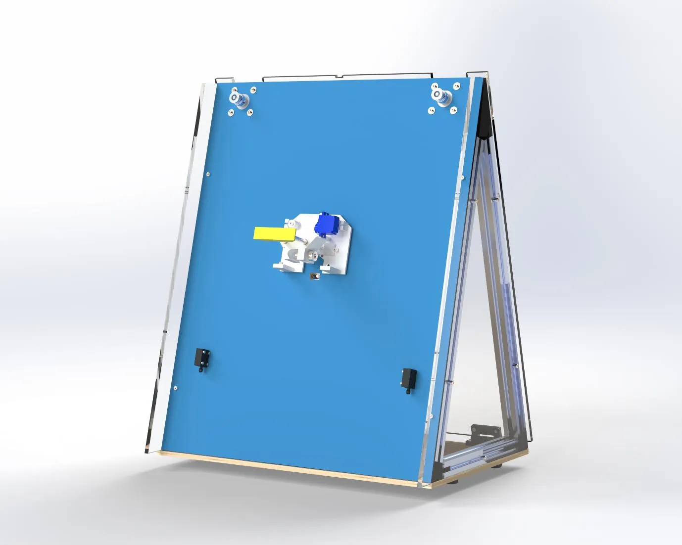
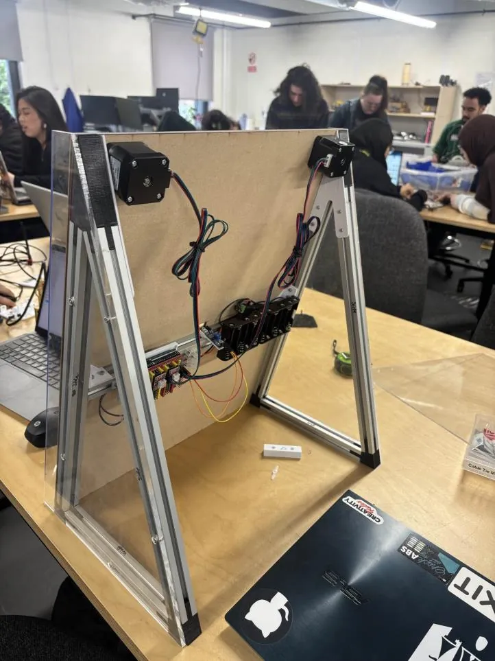
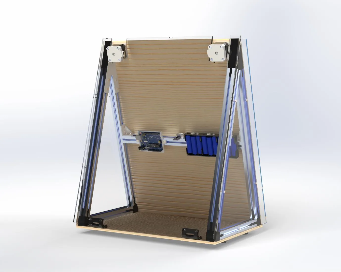
SENKI answers with a vertical, open-frame polargraph. The pen carriage hangs from two belts, each driven by a NEMA 17 stepper at the top of the board, and counterweights keep the belts taut. The frame is aluminium extrusion reused from an old display cabinet, every joint is a screw into a T-nut, and every printed part carries a QR code and a part number.
If a part can't be unscrewed, identified and bought again, the product has already chosen when it will die.
Leading the team that built the best prototype in the cohort
SENKI was a group project, and I led it. I designed the overall machine, from the vertical polargraph concept and the right-to-repair strategy through to the frame, the carriage and how every part comes apart. I wrote the firmware in C++, turning the kinematics into the functions that drive the steppers, read the paper sensor and lift the pen.
Every member of the team modelled parts, and I worked alongside each of them in CAD, refining their designs so they printed reliably on an FDM printer: orientation, wall thickness, tolerances for screws and heat-set inserts, and features that print without supports. That kept the whole machine consistent, and it meant everyone's work made it into the final build.
Leading the group meant keeping a clear direction while making sure each person was supported: breaking the work into pieces people could own, helping whenever someone got stuck, and pulling the mechanical, electronic and software sides together into one working machine. The result was judged the best prototype in the cohort.
Set the direction
Owned the concept, the repairability strategy and the plan, and kept the team moving towards one working prototype.
Designed the whole machine
Frame, motion system, carriage and modular layout, with every part designed to be unscrewed, identified and replaced.
Wrote the firmware
C++ on the Arduino: inverse and direct kinematics, stepper control, the IR paper check and the servo pen lift.
Co-designed every part
Worked through each teammate's CAD with them to optimise it for FDM printing, so every contribution made the final build.
Seven musts and six principles
The brief came in two parts. Seven compulsory user requirements defined what the machine had to do. Six optional repairability criteria described how a repairable product should behave, and the team adopted all six as goals.
Compulsory requirements
- A paper feed system with a sensor that detects paper
- A 2D pen plotter, not an inkjet or laser system
- Battery powered where possible
- An Arduino with the x, y and z motors and sensors it needs
- Low-cost or recycled components wherever possible
- Key components analysed with engineering fundamentals
- Demonstrate the simple function of drawing a line with a pen
Repairability criteria
- Cases open with screws and latches, never industrial adhesive
- The parts most likely to break are the easiest to reach
- Internal parts are standard and independently replaceable
- Repair instructions are free and public
- Every part is labelled with a generic name and ID number
- Parts are generic, so any manufacturer's replacement fits
What users need, ranked
As a group we turned the brief into fourteen user needs and ranked each from 1 (most important) to 5. Ease of disassembly, a stable structure, precision and compatibility with many pens all came out on top, ahead of plotting speed.
| Importance | User needs |
|---|---|
| 1 · Highest | Easy to disassemble · Stable structure · Precision · Compatible with many pens |
| 2 | Repair instructions · Ease of use · Low price · Plots on different paper sizes |
| 3 | Durable parts · Generic parts for easy repair · Accessible screws and components · Clear, readable part labels |
| 4 | A4 paper feed · Time taken to plot |
Product specification
Each need became a measurable target, with a marginal value the product had to meet and an ideal value to aim for.
| Metric | Importance | Marginal | Ideal |
|---|---|---|---|
| Cost of components | 1 | < £25 | £15 |
| Unwanted movement of the plotter | 1 | < 2 mm | 0 mm |
| Lifespan | 1 | > 2 years | 6 years |
| Pen holder range for different utensils | 2 | 10–20 mm | 7–50 mm |
| Disassembly time | 3 | < 30 min | 20 min |
| Motor accuracy | 3 | > 100 steps | 200 steps |
| Paper thickness accepted | 4 | 80–200 gsm | 50–400 gsm |
| Weight of device | 5 | < 5 kg | 3 kg |
| Power consumption | 5 | < 15 W | 10 W |
Needs, ranking and specification were completed as a group.
Why things don't get repaired
Research into design for repair kept returning to the same five barriers. A product can be technically repairable and still end up in landfill if any one of them is left in place.
Knowledge
People don't know how the product works, so they don't know where to start.
Access
Spare parts and technical information are missing, or locked behind restrictive contracts.
Economics
Repair costs too much compared with buying new, so there is no incentive.
Attachment
Owners have no emotional or economic attachment to the product, so they let it go.
Design
Nothing in the design or manufacture actually promotes repair: no access, no standard parts, no labels.
Learning from Fairphone
Fairphone's modular smartphone tackles all five barriers [2]. It publishes repair guides, keeps spare parts and technical information available, prices those parts so repair is worth it, builds loyalty through ethical manufacturing, and lets owners swap modules themselves.
It has also stayed niche. It costs more than leading brands and trades away some performance, and keeping many different modules in stock in every region is a hard supply-chain problem. Repairability has to be designed in a way that does not depend on one company's warehouse.
QR codes on every part
iFixit and Microsoft have started printing QR codes on internal components, such as those inside the Surface Laptop 7, each linking to a repair page and a place to buy the part [6]. It makes identification easy, but the longevity is questionable: if the company or its website disappears, the codes lead nowhere. SENKI keeps the QR codes but pairs each one with a printed part number, and publishes the hardware and software openly, so the information survives without the original maker.
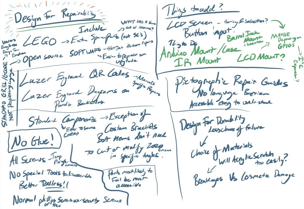
Open-sourcing both the hardware and the software became the thread through everything. It removes proprietary restrictions on modification and repair, and it reduces dependence on custom-made parts, so repairs stay affordable.
Cardboard first
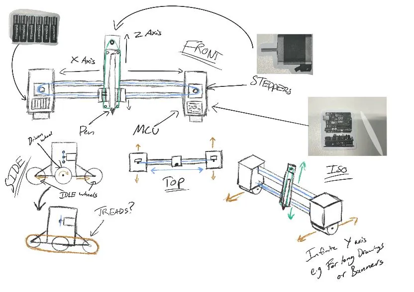
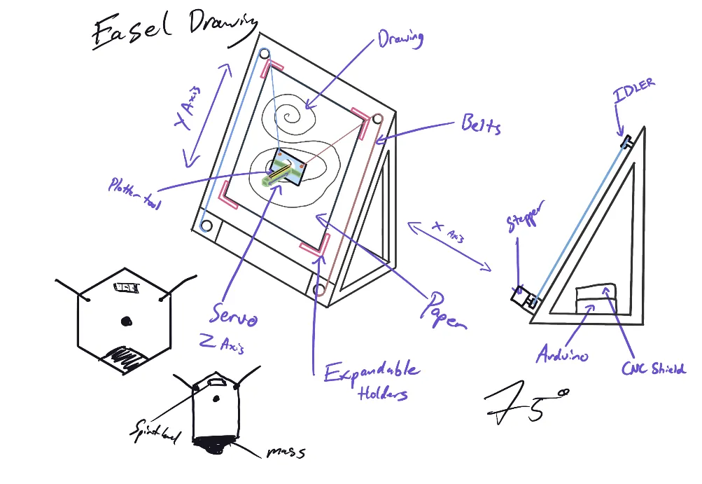
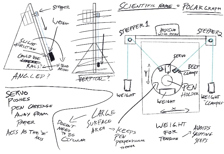
Ideation sketches explored flat-bed and easel layouts before settling on a vertical design inspired by the Maslow CNC router, which hangs its cutting head from two chains across a large upright sheet [3]. A hanging carriage needs no long linear rails, so the frame stays light and the drawing area can grow with the board.
Model V1: does it stand up?
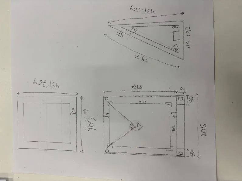
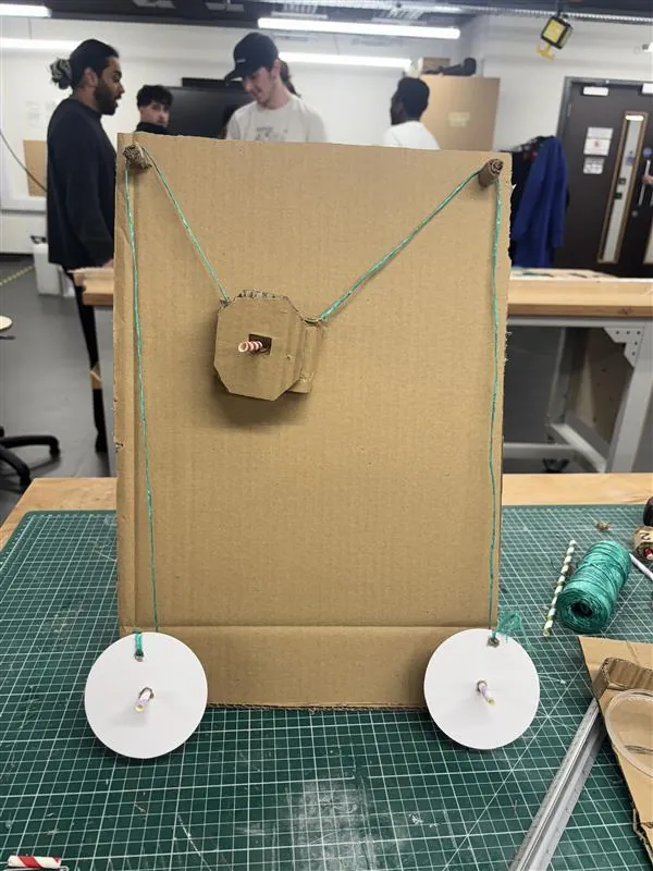
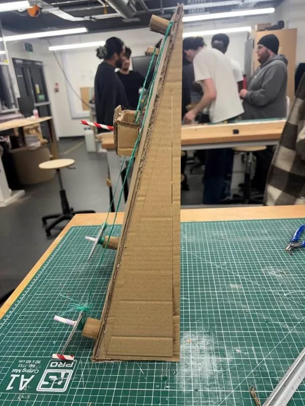
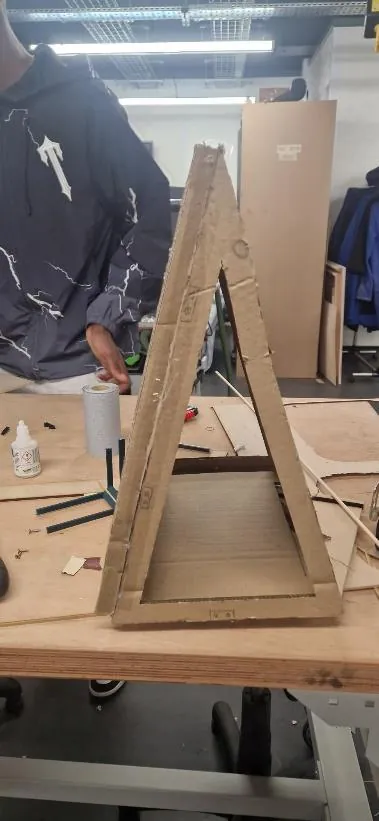
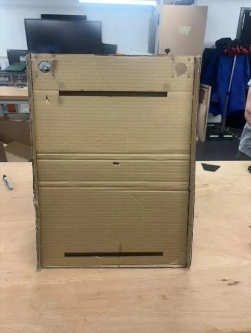
The first cardboard model tested whether a Maslow-style system could work at desk scale. It identified two problems straight away: the frame was unsteady from the side, and the stepper motors were in the wrong place. The carriage size had also not been allowed for, so it could not reach the edges of an A4 sheet, and the dimensions were reworked.
Model V2: motors up, counterweights on
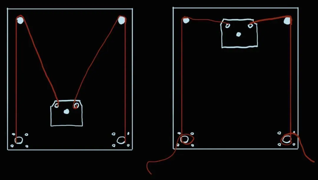
With the motors low, slack belt would wrap and tangle around them. Moving both motors to the top of the board fixed that, and a counterweight on the free end of each belt keeps it taut. The new layout also balanced the weight of the motors across the frame, and the sides were extended to give the counterweights room to hang.
From hot glue to extrusion
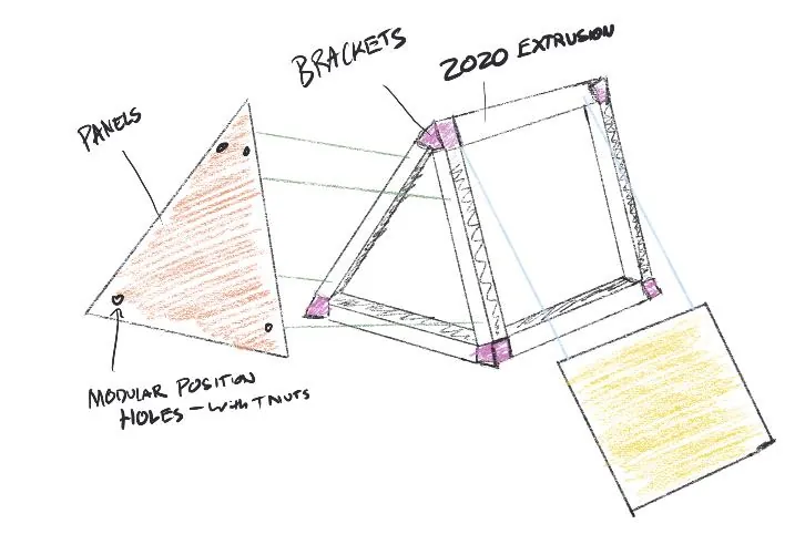
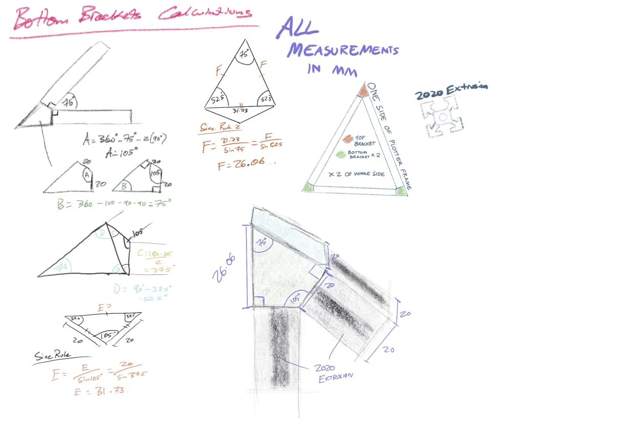
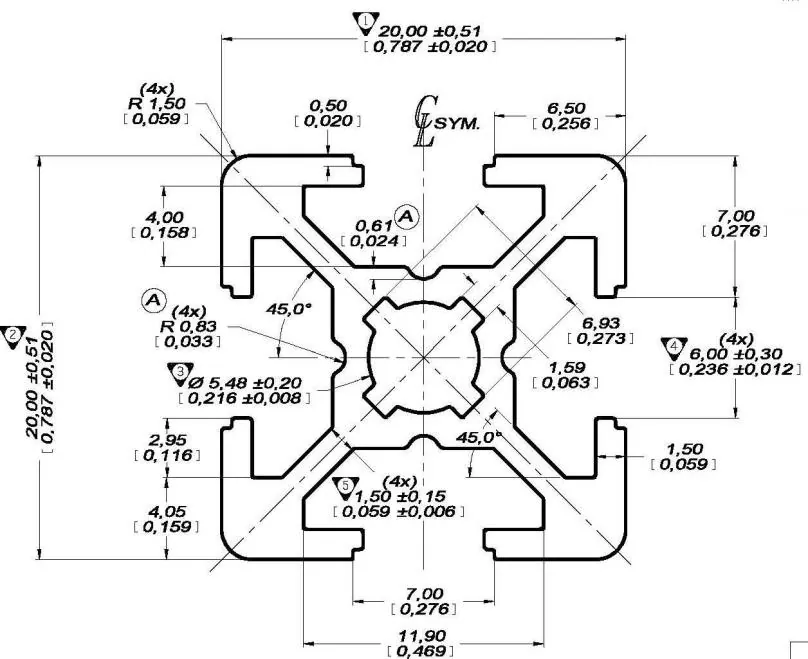
The cardboard models were hot-glued, which fails the brief outright. On V2 the brackets that would join each panel were drawn on, and that led to a frame of 2020 aluminium extrusion with printed brackets at each corner. Because every panel screws into a T-nut that can slide anywhere along the extrusion, mounting holes can go wherever they are needed.
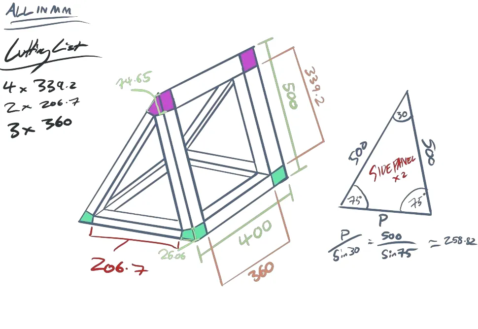
The models also settled the board angle. A 75° incline gives a nicer viewing angle and stops the counterweights swinging as the carriage moves, at the cost of a little more friction than a truly vertical board.
Turning belt lengths into lines
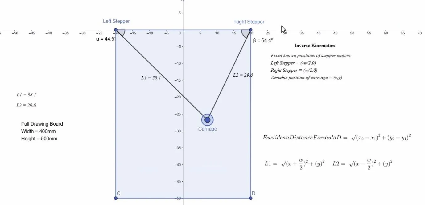
A polargraph has no x or y axis. Each motor only changes the length of its own belt, so drawing a straight line means solving for two belt lengths, many times a second.
Belt length
The worst case is the carriage in the far bottom corner of a 400 × 500 mm board. The GT2 pulley measured 15 mm across, so 180° of belt wrapped around it adds an arc to the diagonal.
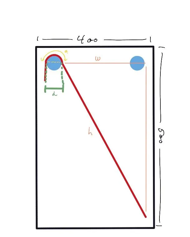
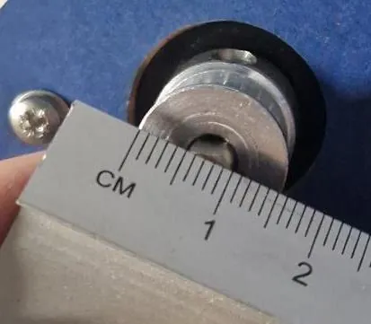
Per belt, plus extra in reality to allow for the clamps at each end.
Polargraph kinematics
Put the origin at the top centre of the board, with the left motor at (−w/2, 0), the right motor at (w/2, 0) and the carriage at (x, y), measured downwards. Inverse kinematics, from a point to two belt lengths, is Pythagoras twice [1]:
Direct kinematics runs the other way, from two belt lengths back to a point. Subtracting the squares cancels y and gives x; adding them gives y:
Drag the carriage below to see both directions at once. The lengths update as it moves, and the point recovered from those lengths lands back on the carriage.
Board width w = 400 mm, as in the belt calculation. The report also links an interactive GeoGebra version of these equations [4].
Forces in the frame
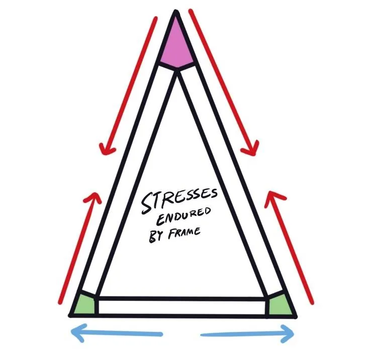
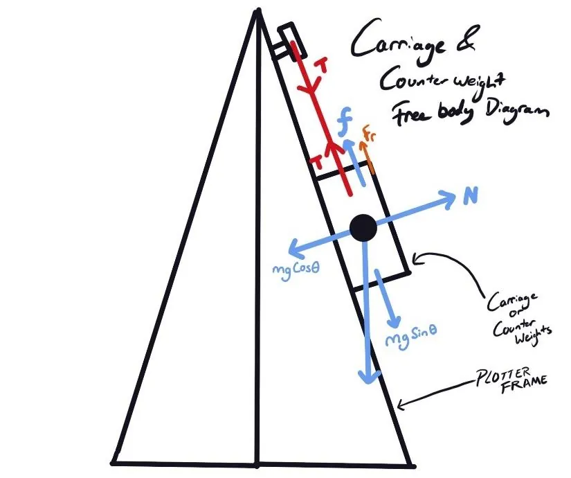
Under load the A-frame's sloping sides are in compression and the base ties are in tension. The carriage and the counterweights share the same free body diagram: belt tension, weight, the normal force from the board and friction along its 75° face.
Choosing a stepper
The cheap 28BYJ-48 has a finer step thanks to its internal gearbox, 4096 steps per revolution against 200 for a NEMA 17. But it is slow and has about a tenth of the torque, and the motors have to lift the carriage and its counterweights. The NEMA 17 won.
| Feature | NEMA 17 | 28BYJ-48 |
|---|---|---|
| Voltage | 12–24 V | 5 V |
| Torque | High, 40–59 N·cm | Low, 3–4 N·cm |
| Step | 1.8°, 200 steps per revolution | 5.625° with gearing, 4096 steps per revolution |
| Speed | Fast | Slow |
| Size | Large, heavy | Compact, light |
| Cost | £10–£30 | £2–£5 |
The right material for each job
Materials were judged on three groups of criteria: technical (strength, dimensional accuracy, resistance to warping), non-technical (cost, finish, perceived value) and manufacturing (laser cutting or printing, joining method, scalability).
| Material | Strength | Precision | Cost | In practice |
|---|---|---|---|---|
| 3 mm MDF | 30–50 MPa | ±0.2 mm | Low, £2–5/m² | Cheap and smooth, easy to paint; absorbs moisture, weaker than plywood |
| 3 mm plywood | 40–80 MPa | ±0.15 mm | Low–medium, £3–8/m² | Stronger, real grain; warps over time across a large panel |
| 6 mm acrylic | 70–130 MPa | ±0.1 mm | Medium, £10–20/m² | Strong and transparent; brittle and more expensive |
| PLA (printed) | 45–65 MPa | ±0.05 mm | Low–medium, £10/kg | Precise and customisable; not for high stress or heat |
| ABS (printed) | 40–65 MPa | ±0.05 mm | High, £25/kg | Tougher than PLA and can be smoothed; hard to print, warps |
Each part got the material that suited it. PLA for the brackets, carriage and clamps: economical, precise and easy to remix. MDF for the drawing board, since plywood would warp across such a large area and MDF is cheap for owners to swap and personalise. Acrylic for the back, base and side panels, so the open-plan mechanism stays visible.
Borrowing from iFixit, IKEA, LEGO and Creality
Each repairability decision borrows from a company that already does one thing well.
Modular
Like the Ender 3 printer, SENKI is a set of modules on an extrusion frame. Any part can be replaced or upgraded without touching the rest, and the electronics use plug-and-play connectors.
Nothing proprietary to fix it
Phillips and hex-head metric screws throughout: M3 everywhere, M2 only where the SG90 servo demands it and M8 for the pen clamp. Counterweights are standard 20 g slotted lab masses that can be swapped while it runs.
Spares in the box
A bag of common spare parts comes with the plotter, removing the hardest step of any repair: finding the part.
Instructions anyone can read
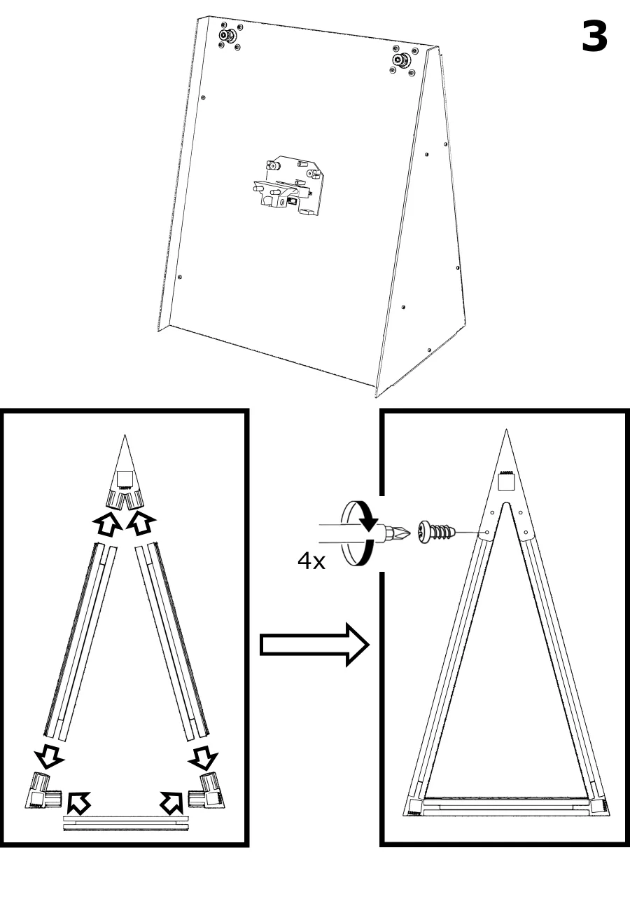
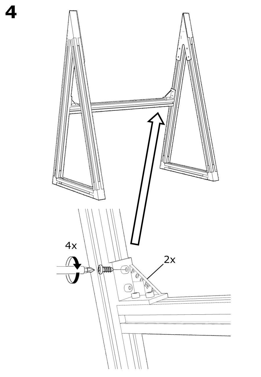
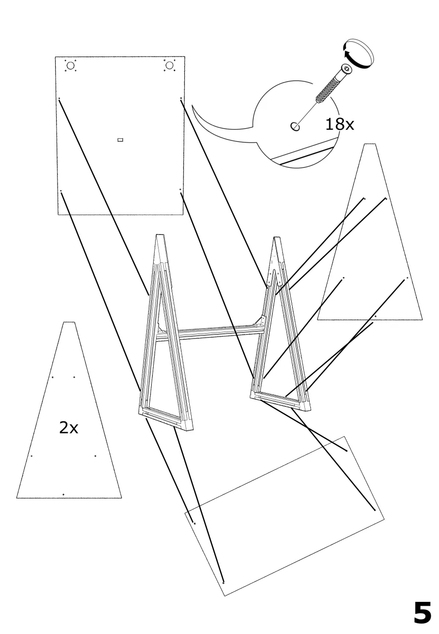
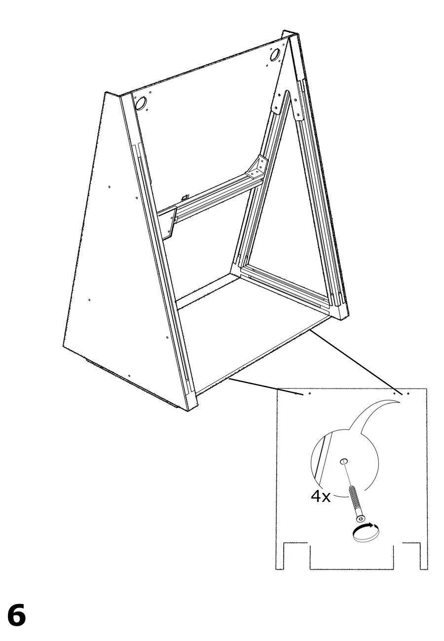
Picture-led assembly steps work in any language and double as disassembly steps when read in reverse.
A frame with a second life
The 2020 aluminium extrusion was reused from a display cabinet. Because nothing is glued or welded, it can be unbolted again at the end of SENKI's life and become something else. That is the circular economy at the scale of one product: the most valuable material in the machine was never new and never has to be thrown away.
The T-nuts that hold it together are simple, self-locking, reusable and cheap, and they let any part be mounted anywhere along the extrusion. Every electronic part is an off-the-shelf component available at a reasonable price from many suppliers.
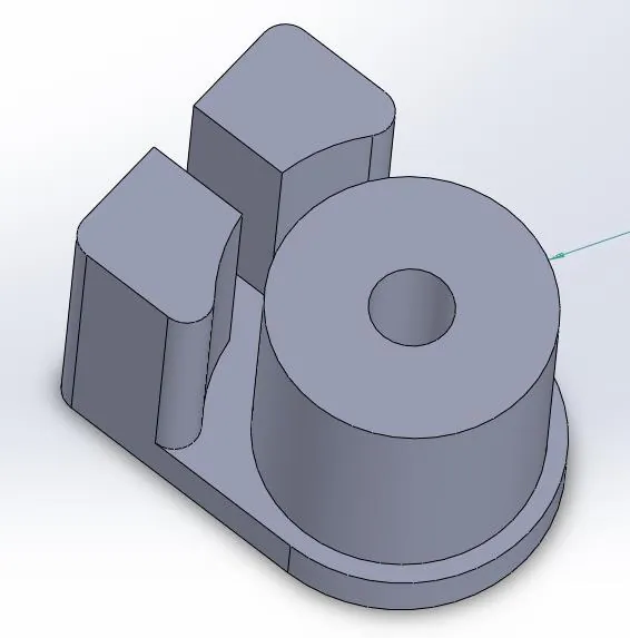
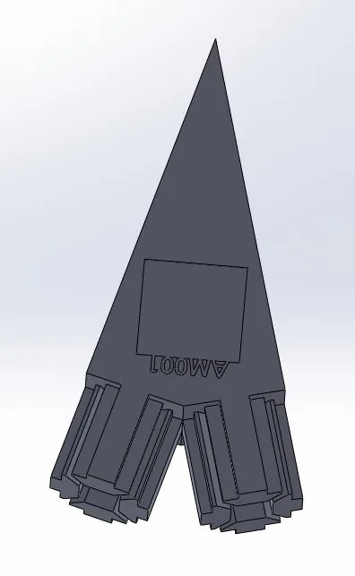
Every part with a QR code and a number
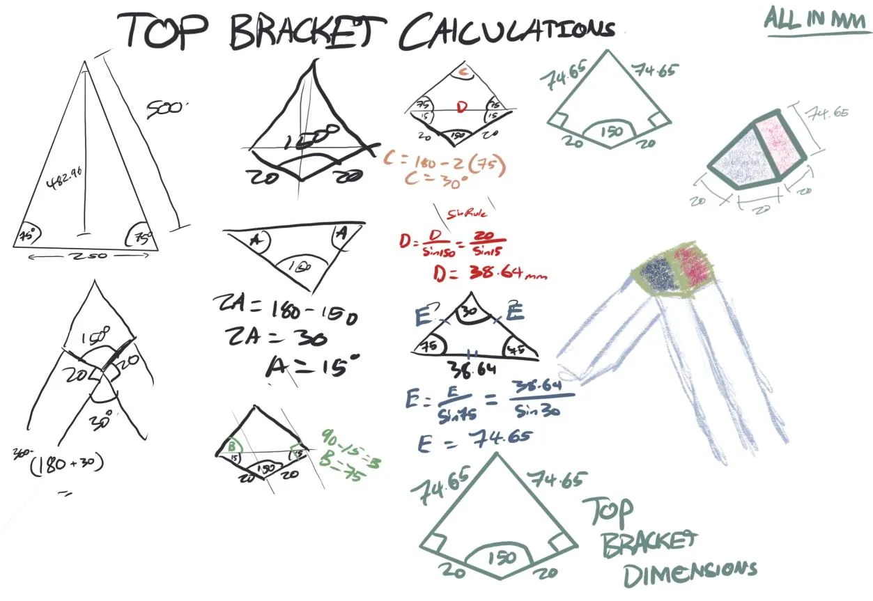
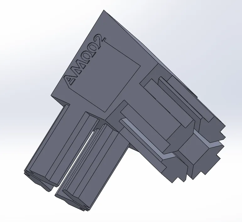
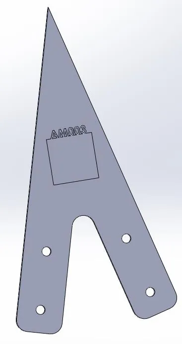
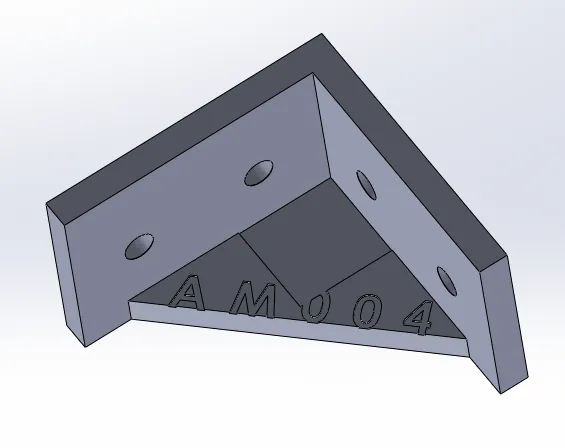
Each part was modelled in SolidWorks. The custom brackets reserve a 20 × 20 mm space for a QR code and carry a printed part number, so an owner can identify a broken part without the original documentation.
Assembly
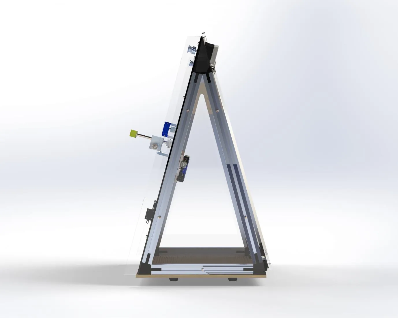
The full assembly uses standard, advanced and mechanical mates with sub-assemblies, so every component's position and range of movement is defined.
An Arduino, a CNC shield and an IR eye
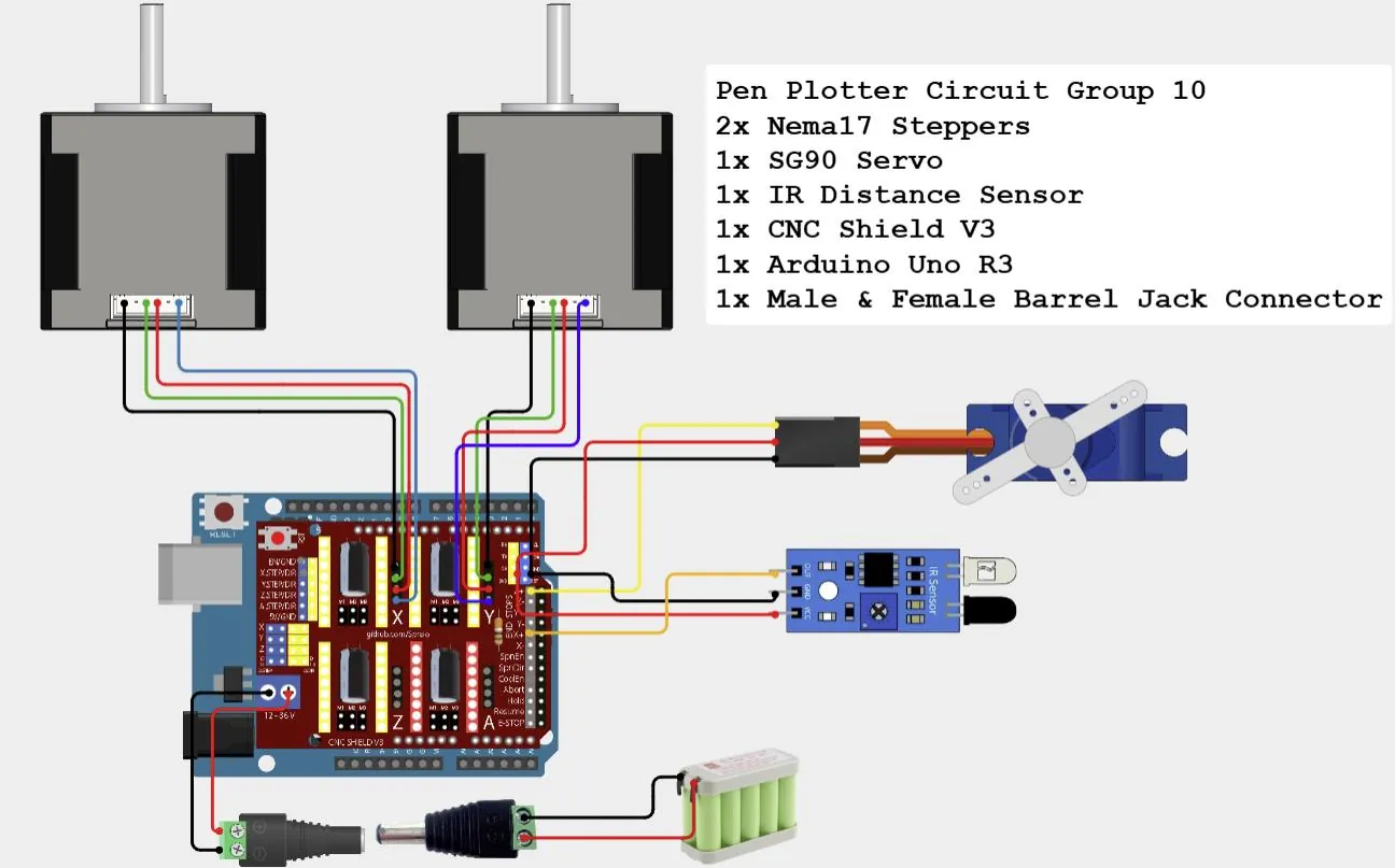
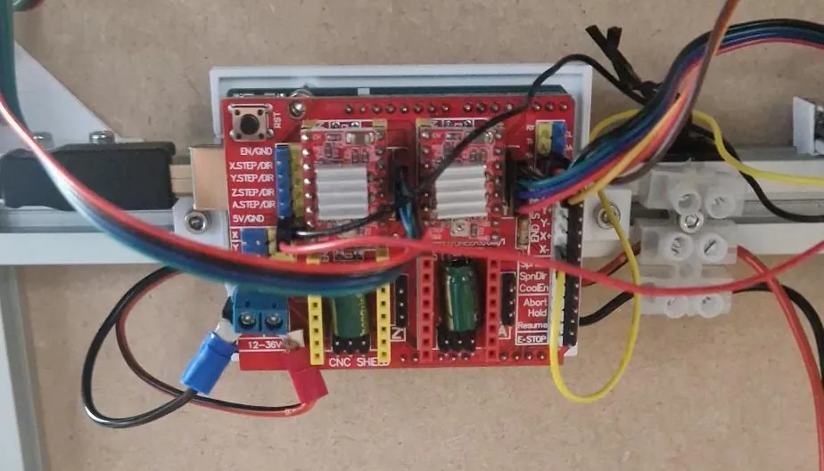
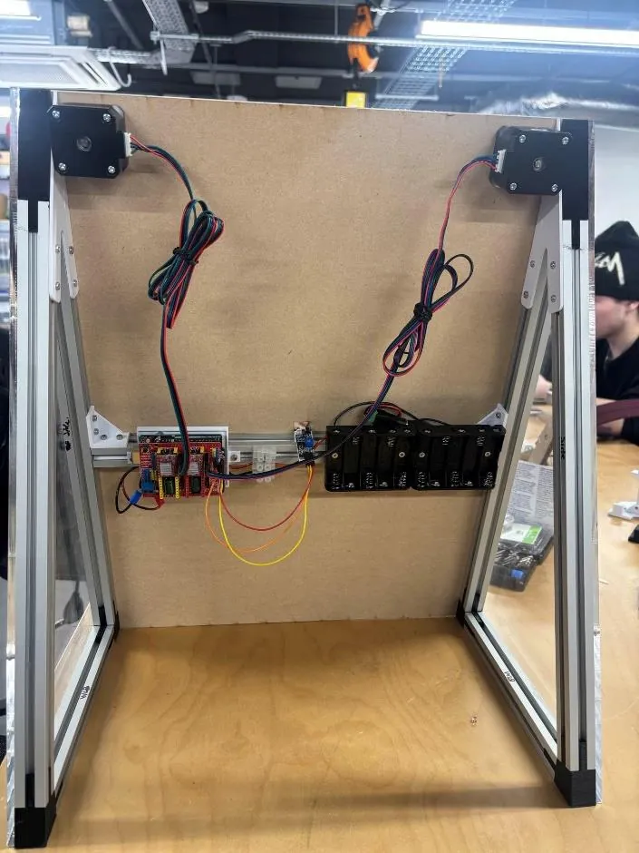
An Arduino Uno with a CNC Shield V3 drives the two NEMA 17s through A4988 drivers on the X and Y channels. An IR sensor on the X end-stop pin detects paper, and an SG90 servo on the Z end-stop pin lifts and lowers the pen. The shield takes 12 V from a battery and the Arduino is powered separately. The circuit was drawn in Cirkit Designer, an alternative to Tinkercad.
From equations to firmware
I wrote the firmware in C++. The kinematics became four small functions, so the firmware can turn any coordinate into two belt lengths and back. The AccelStepperWithDistances library then moves each stepper by a distance in millimetres rather than a count of steps.
// Inverse kinematics: point to belt lengths
float calcL1(float x, float y) { return sqrt(pow(y, 2) + pow(x + width/2, 2)); }
float calcL2(float x, float y) { return sqrt(pow(y, 2) + pow(x - width/2, 2)); }

// Direct kinematics: belt lengths to point
float calcX(float l1, float l2) { return (pow(l1, 2) - pow(l2, 2)) / (2 * width); }
float calcY(float l1, float l2) { return sqrt(pow(l1, 2) - pow(calcX(l1, l2) + width/2, 2)); }
Plotting only starts when the IR sensor sees paper. Sending s over serial checks the sensor first:
if (input.equalsIgnoreCase("s")) {
  if (sensorState == LOW) {
    loopActive = true;
    Serial.println("Paper Detected");
  } else {
    Serial.println("No Paper");
  }
}From render to workshop
The prototype was built with both additive and subtractive manufacturing: printed PLA brackets, carriage and clamps, laser-cut panels and the reused extrusion frame. All of it is listed on a 34-line bill of materials.
| Module | Main parts | Materials |
|---|---|---|
| Frame | 5 lengths of 2020 extrusion (339.2, 206.7 and 360 mm), 2 top, 4 bottom, 2 top sub and 2 L brackets, 20 M3 T-nuts | Reused aluminium, PLA |
| Panels | Front drawing board 400 × 500 mm; back, bottom and 2 side panels; 2 polypropylene hinges; 4 magnets | MDF, acrylic |
| Motion | 2 NEMA 17 steppers, 2 GT2 belts at 671.33 mm, 2 belt clamps, 2 weight holders with slotted masses | Metal, Kevlar-reinforced PU, PLA |
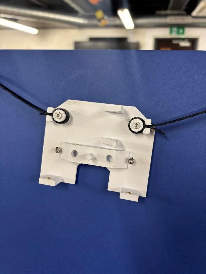
| Pen carriage | Carriage, three-part pen mechanism, 2 steel guide rods, M8 pen clamp screw, SG90 servo, 8 M3 heat-set inserts | PLA, stainless steel, brass |
| Electronics | Arduino Uno R3, CNC Shield V3, 2 A4988 drivers, IR distance sensor and mount, DC barrel jack | Off-the-shelf PCBs |
| Fasteners | 55 M3 pan-head screws (6–16 mm), 8 M2 × 10 screws | Steel |
Condensed from the bill of materials, which was completed as a group.
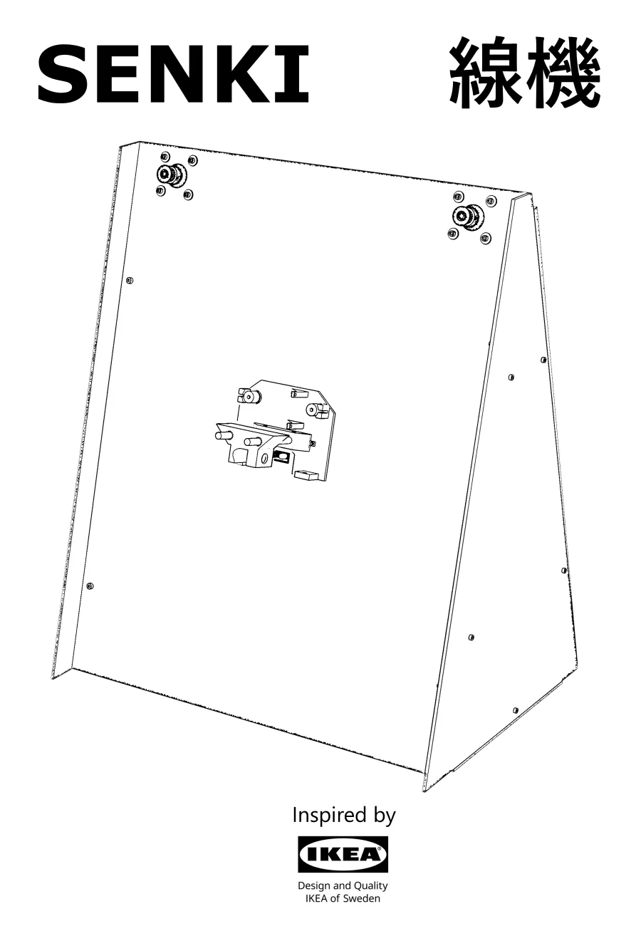
An IKEA manual for a machine
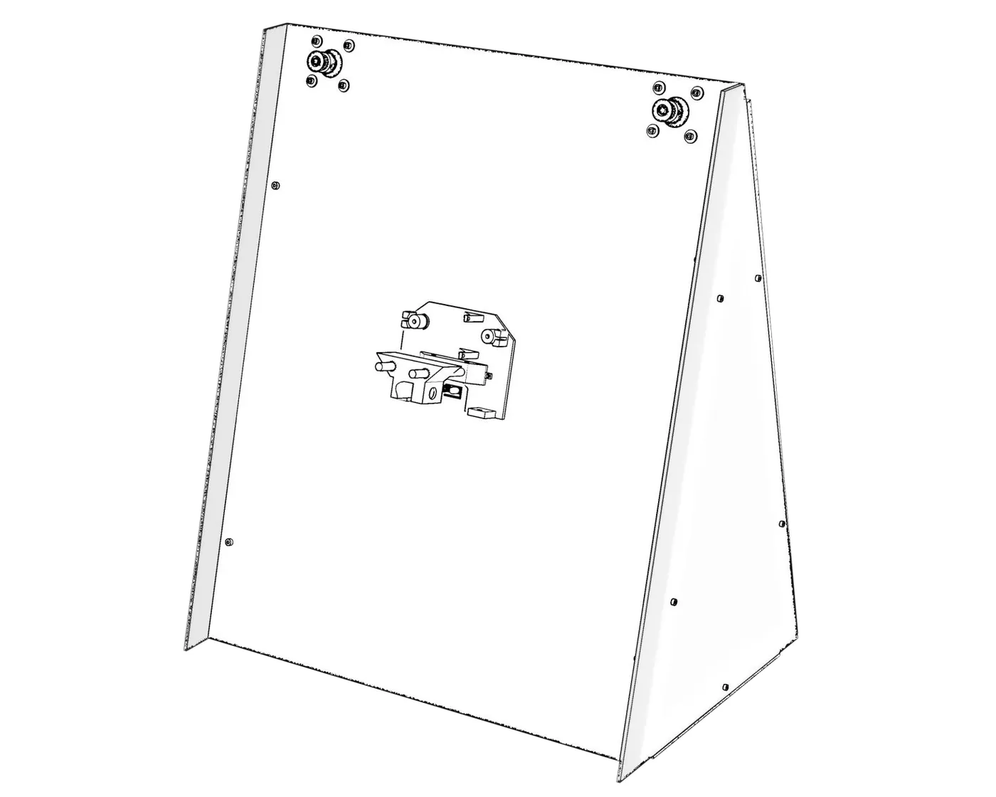
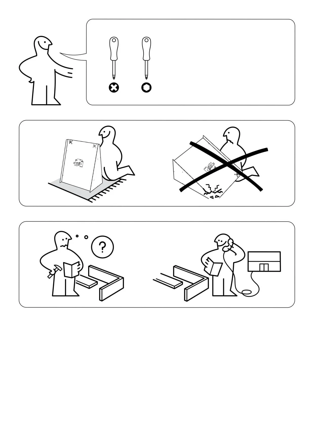
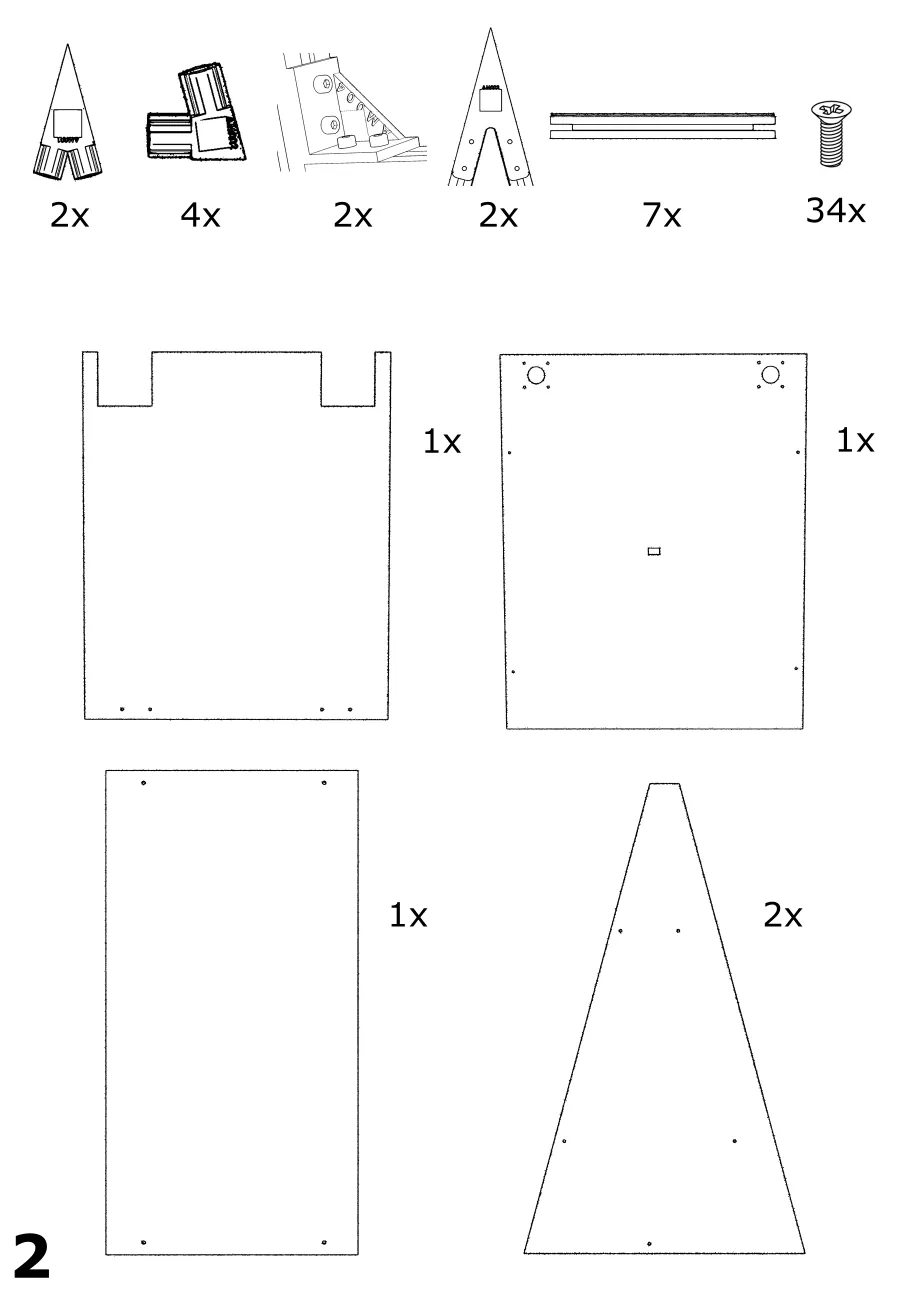
Clear, step-by-step instructions give owners the confidence to repair their own devices, but only if anyone can follow them. Pictographic guides like IKEA's need no shared language [5], and iFixit's teardown guidelines show how much a good picture can carry [8]. Not everything can be shown with pictures alone, so the guide balances images with as little text as possible.
The SENKI guide is written as assembly instructions. Read backwards, it is the disassembly guide, so every repair starts from a document the owner already has.
Five barriers, five answers
Measured against the five barriers to repair that started the project, here is how SENKI responds to each.
| Barrier | SENKI's answer |
|---|---|
| Knowledge | Pictographic manuals and QR-coded, numbered parts for easy identification and assembly |
| Access | A bag of common spares in the box; standard, easily sourced components; open-source hardware and software |
| Economics | Modular, standardised parts that are cheap to replace; screws and no glue; free guides and spares lower the barrier to entry |
| Attachment | A drawing board and panels that can be recoloured, engraved or remade in another material; an open design that shows the plotting in action; no planned obsolescence |
| Design | Fasteners and no adhesives, universal components, a design broken into modules, labelled parts, and a frame that can be repurposed |
The printed brackets are custom, but open-sourcing them means an owner can send the files to any mainstream 3D printing service for a cheap replacement, or remix them into a plotter of their own. When it isn't drawing, SENKI is meant to be a display piece, showing finished artwork with the pen carriage stowed in its storage compartment. And because the motion system hangs rather than slides, there is no limit to the thickness of material it can draw on, and the design scales to any size of board.
What the prototype taught us to change
| Part | Problem | Next iteration |
|---|---|---|
| Pen carriage | Not enough surface area to stay in contact with the paper the whole time | A larger carriage, ideally in clear acrylic so you can watch the pen while it draws |
| SG90 servo | Not enough torque to lift the pen against its springs | A stronger servo or a different actuator matched to the spring tension |
| Back panel and hinge | The panel doesn't close flush against the frame, and cables have no way out | A new hinge and a cut-out for power and data cables |
| Brackets | 3D printed, which is slow at production scale | Revise for injection moulding, keeping them open source |
| Pen mechanism | Too many printed parts and heat-set inserts | Fewer printed parts and fewer inserts for viable manufacture |
For manufacture, laser-cut panels should be nested to use as much of each sheet as possible, and the whole plotter can be flat-packed to save space and money in shipping.
What SENKI taught me
- Repairability is a set of design decisions, not a feature. It shows up in screw sizes, label space on a bracket and the order of steps in a manual. If it isn't decided early, it can't be added later.
- Cheap models answer expensive questions. Two cardboard models found the tangling belts, the unstable frame and the missing carriage clearance before any aluminium was cut.
- The most sustainable part is the one you didn't buy. Reusing the extrusion from a display cabinet shaped the whole frame, and leaving it unglued means it can be reused again.
- Maths is only finished when it moves something. The kinematics were not done when the equations balanced; they were done when the same functions ran on the Arduino.
- Learn from people who have tried before. Fairphone, Microsoft, IKEA, LEGO and Creality each solved one part of the repair problem, and each also showed a trade-off to avoid.
- Leading is mostly supporting. The best prototype in the cohort came from a team where everyone owned a piece and nobody was left stuck. Setting the direction mattered, but most of the job was helping each person get their part right and fitting it into the whole.
- Prototype to find the next problem. The carriage contact, servo torque and back panel issues only appeared once the machine was real, and they set the brief for the next version.
Sources
- Azevedo, T.C. (n.d.) VBot calculations. nexp.pt
- Causeartist (n.d.) Case study: Fairphone, the ethical and sustainable smartphone. causeartist.com; see also WhizGenius (n.d.) Fairphone repairability and modular design. whizgenius.com
- Maslow CNC (n.d.) About Maslow 4 CNC. maslowcnc.com
- Polargraph calculator (GeoGebra). geogebra.org
- Danzico, L. (n.d.) How IKEA's assembly instructions champion universal design. magenta.as
- Mokhtari, S. (n.d.) From 0/10 to 8/10: Microsoft puts repair front and center. iFixit. ifixit.com
- Rehorst, M. (n.d.) 2 mm pitch GT2 belt clamps. 3dforprint.com
- iFixit (n.d.) Guidelines for creating a teardown. ifixit.com
- nanoblock (n.d.) Why do LEGO sets have extra pieces? nanoblockus.com